
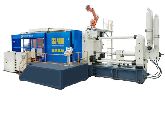
LARGE COLD CHAMBER DIE CASTING MACHINE
| No. | Item | Unit | CSC1250 | CSC1600 | CSC2000 | CSC2500 | CSC3000 | CSC3500 | CSC4000 | CSC5000 | CSC6000 | |||||||||||||
| 1 | Clamping Force | KN | 12500 | 16000 | 20000 | 25000 | 30000 | 35000 | 40000 | 50000 | 60000 | |||||||||||||
| 2 | Space between Tie Bars | mm | 1100X1100 | 1184X1184 | 1350×1350 | 1500×1500 | 1650×1650 | 1750×1750 | 1850×1850 | 1950×1950 | 2320×2320 | |||||||||||||
| 3 | Die Opening Stroke | mm | 1000 | 1200 | 1400 | 1500 | 1500 | 1600 | 1700 | 1800 | 2300 | |||||||||||||
| 4 | Die Height〔min.-max.〕 | mm | 450-1200 | 500-1400 | 650-160 | 800-1800 | 800-2000 | 850-2050 | 900-2100 | 900-2200 | 1300-2400 | |||||||||||||
| 5 | Platen Size (H x V) | mm | 1740X1740 | 2000X2000 | 2150×2150 | 2350×2350 | 2620×2620 | 2780×2780 | 2920×2920 | 3080×3080 | 3570×3570 | |||||||||||||
| 6 | Ejector Force | KN | 590 | 640 | 650 | 750 | 900 | 900 | 1000 | 1000 | 1100 | |||||||||||||
| 7 | Ejector Stroke | mm | 200 | 250 | 300 | 300 | 300 | 300 | 350 | 400 | 400 | |||||||||||||
| 8 | Max. Injection Force | KN | 1080 | 1250 | 1550 | 1700 | 2100 | 2410 | 2560 | 2760 | 3133 | |||||||||||||
| 9 | Plunger Stroke | mm | 880 | 930 | 960 | 1080 | 1180 | 1400 | 1500 | 1600 | 1700 | |||||||||||||
| 10 | Shot Position | mm | -160 | -320 | -175 | -350 | -175 | -350 | -200 | -400 | -250 | -450 | -300 | -600 | -300 | -600 | -300 | -600 | -400 | -800 | ||||
| 11 | Plunger Diameter | mm | 100-140 | 110-150 | 130-170 | 140-180 | 150-190 | 160-200 | 170-210 | 180-220 | 190-250 | |||||||||||||
| 12 | Shot Weight | Kg/(Al) | 13-25.4 | 17-32 | 22-41 | 30.3-50.1 | 39.1-62.7 | 52.7-82.4 | 55-88 | 76-114 | 85-150 | |||||||||||||
| 13 | Casting Pressure | Mpa | 137-70 | 132-71 | 116-68 | 117-71 | 119-73 | 120-77 | 112-74 | 110-73 | 110-63 | |||||||||||||
| 14 | Casting Area | cm2 | 910-1785 | 1200-2240 | 1750-3030 | 2270-3785 | 1520-4110 | 2910-4540 | 3590-5400 | 4540-6850 | 5000-9500 | |||||||||||||
| 15 | Max. Casting Area (400kg/cm2) | cm2 | 3125 | 4000 | 5000 | 6250 | 7500 | 8750 | 10000 | 12500 | 15000 | |||||||||||||
| 16 | Shot Flange Diameter | mm | 240 | 260 | 260 | 280*30 | 280*30 | 320 | 320 | 340 | 400 | |||||||||||||
| 17 | Height of Shot Flange | mm | 25 | 25 | 25 | 30 | 30 | 35 | 35 | 35 | 40 | |||||||||||||
| 18 | Plunger Penetration | mm | 350 | 360 | 400 | 450 | 530 | 600 | 650 | 700 | 750 | |||||||||||||
| 19 | System Working Pressure | Mpa | 16 | 16 | 16 | 16 | 16 | 16 | 17 | 17 | 17 | |||||||||||||
| 20 | Motor Capacity | Kw | 74 | 74 | 90 | 135 | 165 | 190 | 220 | 240 | 360 | |||||||||||||
| 21 | Oil Tank Capacity | L | 2500 | 2600 | 2800 | 3700 | 4200 | 4800 | 5200 | 6000 | 8000 | |||||||||||||
| 23 | Machine Dimension | m | 11X4X4.1 | 11.9X4.1X4.3 | 12.8×4.4×4.5 | 16×5.4×5.3 | 16×5.4×5.3 | 16×5.4×5.3 | 17×5.6×5.7 | 18.3×5.7×5.9 | 20×6.8×6.0 | |||||||||||||
PLC CONTROL UNIT
Professional programming control use with famous worldwide branded controllers. Standard feature with 12 inch touch screen control & real time monitoring curve, to provide more accurate data for reference or modify setting purposes.
CLAMPING UNIT
High strength and wear resistant casting platens and toggles, toggle system designs with double link tie bar guidance, brings even stress distribution and steady mechanism. Standard with hydraulic driven gear type die height adjustment for convenient operation & accurate setting.
HYDRAULIC SYSTEM
Providing with Servo-Hydraulic power system, compare to traditional vane pump design can be energy up to 70%. Besides saving the production and operating costs, the servo motor brings the effect of keeps low oil temperature, to keep the machine long time usage with under high repeat operation accuracy.
INJECTION UNIT
Servo motor control proportional flow control accuracy is more accurate than traditional oil valve; comes with a feedback signal to the controller and self automatic correction function to ensure the production quality.
ADVANTAGES
- Significantly improve the efficiency of the die-casting machine (high energy saving)
- Enhance the operation repeat accuracy and stability
- Improve product cycle time, increase the production volume
- Reduce the rejection rate
- Improve the efficiency with application of automation
- Suitable to use under metal dust, harsh environment, high temperature working conditions
- Production real-time action fault detection, protection and alarm functions
STANDARD ACCESSORIES
1. FANUC Control Motors
2. 4” Spindle Bore
3. Auto 4 Steps Spindle Speed Change
4. H4 0r V8 Turret
5. Auto Coolant, Hydraulic and Lubrication System
6. Splash Guard
7. Hydraulic Tailstock
8. Work Light
9. Tool Box with Tools
OPTIONS
1. Extra Spindle Bore and Motor
2. Spindle Oil Chiller
3. Hydraulic / Manual Chuck
4. C Axis or Spindle 1/15 Degree Indexing
5. Driving tool Turret
6. Steady Rest
7. Follow Rest
8. Special Boring Bar Holder
9. Higher Coolant Pressure
10. Chip Conveyor
11. CE Mark
12. Transformer