
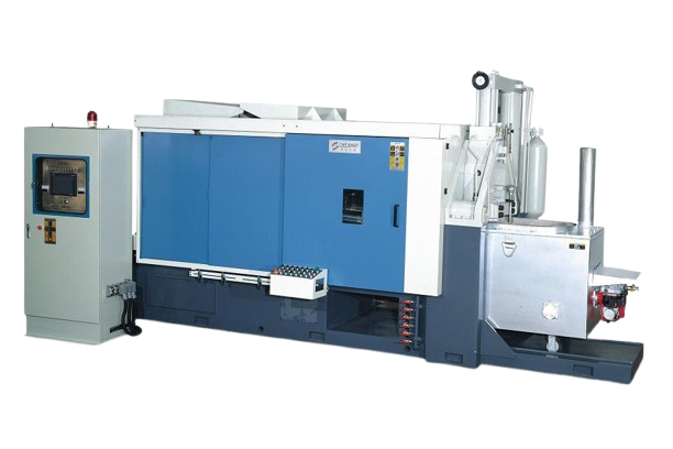
HOT CHAMBER DIE CASTING MACHINE
| NO. | ITEM | UNIT | CSS39 | CSS50 | CSS90 | CSS138 | CSS188 | CSS200 | CSS280 | CSS400 | CSS650 | |||||||||
| 1 | Clamping Force | kN | 400 | 500 | 900 | 1380 | 1880 | 2000 | 2800 | 4000 | 6500 | |||||||||
| 2 | Space between Tie Bars | mm | 280x280 | 310x310 | 365x365 | 410x410 | 480x480 | 510x510 | 580x580 | 620x620 | 775x775 | |||||||||
| 3 | Die Opening Stroke | mm | 215 | 220 | 250 | 305 | 400 | 350 | 470 | 550 | 770 | |||||||||
| 4 | Die Height〔min.-max.〕 | mm | 100-330 | 100-330 | 120-360 | 150-450 | 200-550 | 200-550 | 250-650 | 250-700 | 350-880 | |||||||||
| 5 | Platen Size (H x V) | mm | 450x450 | 460x460 | 550x550 | 620x630 | 730x750 | 750x770 | 900x920 | 970x985 | 1190x1190 | |||||||||
| 6 | Ejector Force | kN | 30 | 45 | 45 | 70 | 89 | 109 | 155 | 210 | 250 | |||||||||
| 7 | Ejector Stroke | mm | 60 | 60 | 65 | 76 | 100 | 87 | 110 | 125 | 150 | |||||||||
| 8 | Injection Force | kN | 40 | 60 | 66 | 110 | 130 | 133 | 180 | 210 | 240 | |||||||||
| 9 | Injection Stroke | mm | 125 | 130 | 130 | 138 | 150 | 160 | 190 | 190 | 280 | |||||||||
| 10 | Nozzle Traverse Stroke | mm | 230 | 190 | 190 | 200 | 220 | 260 | 230 | 230 | 376 | |||||||||
| 11 | Shot Position | mm | 0 | -40 | 0 | -50 | 0 | -50 | 0 | -80 | 0 | -80 | 0 | -80 | 0 | -125 | 0 | -125 | 0 | -100 |
| 12 | Plunger Diameter | mm | 40 | 45 | 40 | 45 | 50 | 55 | 55 | 60 | 65 | 70 | 65 | 70 | 70 | 80 | 80 | 90 | 90 | 100 |
| 13 | Shot Weight | Kg(Zn) | 0.8 | 1.0 | 0.9 | 1.1 | 1.1 | 1.2 | 1.7 | 2.0 | 2.5 | 2.9 | 2.6 | 3.1 | 3.7 | 4.8 | 4.8 | 6.1 | 9.0 | 11.1 |
| 14 | Melting Pot Capacity | Kg(Zn) | 250 | 300 | 450 | 450 | 450 | 720 | 850 | 850 | 1100 | |||||||||
| 15 | System Working Pressure | bar | 90 | 120 | 110 | 140 | 140 | 140 | 140 | 140 | 160 | |||||||||
| 16 | Motor Capacity | kW | 7.5 | 7.5 | 11 | 15 | 15 | 18.5 | 22 | 22 | 37 | |||||||||
| 17 | Oil Tank Capacity | L | 200 | 200 | 220 | 320 | 420 | 420 | 600 | 700 | 1200 | |||||||||
| 18 | Nozzle Heater Consumption | kW | 1.3 | 2 | 2.2 | 2.5 | 2.5 | 2.5 | 3 | 4 | 10 | |||||||||
| 19 | Diesel Furnace Consumption | Kg/h | 4 | 4 | 4.5 | 4.8 | 5 | 5.5 | 6.3 | 6.3 | 10 | |||||||||
| 20 | Machine Weight | Ton | 3.2 | 3.5 | 4 | 5.8 | 7.2 | 7.7 | 10 | 16 | 31 | |||||||||
| 21 | Machine Dimension | m | 3.5×1.3×1.9 | 3.6x1.4x1.9 | 4.1x1.5x1.95 | 4.3×1.6×2 | 4.8×1.6×2.1 | 5.3x1.6x2.3 | 5.5×1.7×2.5 | 6.5×1.8×3 | 6.5×1.8×3 | |||||||||
PLC CONTROL UNIT
German Siemens PLC control system with color touch screen provides function as parameters settings&alarm -message display, to ensure machine stable, safe and reliable performance.
CLAMPING AND DIE HEIGHT ADJUSTMENT UNIT
High strength and wear resistant casting platens and toggles, toggle system designs with double link tie bar guidance, brings even stress distribution and steady mechanism.
Standard with hydraulic driven gear type die height adjustment for convenient operation & accurate setting.
HYDRAULIC SYSTEM
Hydraulic system adopts a dual proportional control system of pressure and hydraulic flow, achieves multi-stage pressure and speed control, and low pressure clamping protection. European and Japanese made oil seals could enhance machine reliable operation; imported high-low pressure double pump performs lower noise level with high efficiency.
INJECTION UNIT
2 stages injection controls with piston type accumulator and high flow hydraulic system design, adopts high speed & steady injection, Consumable parts use with good quality material to ensure long service life.
STANDARD FEATURES
Programmable Logic Controller
Low Pressure Die Closing Protective Program
Proportion Speed & Pressure Control For Die Closing & Opening
Import Brand Diesel Burner
Hydraulic Nozzle Disengagement
Colour touch Screen Display
Two phase Injection Control
OPTIONAL FEATURES
1. Servo Drive System
I. Improve machine mechanical efficiency and energy savings.
II. Enhance machine operation precision and speed, thereby further improving the casting quality and cycle time.
III. Effectively reduce the hydraulic oil temperature improve the stability of the machine and prolong the usage life.
IV. Enhanced design suitable to use under metal dust harsh environment, high temperature working conditions.
2. Hydraulic Platform (Two injection Position)
3. Core Pulling Device
4. Natural Gas / LPG or Electric Furnace
5. Automatic Safety Door
6. Injection Monitoring System
7. Die Temperature Monitoring Device
EQUIPMENTS
1. Central Furnace & Charging System
I. Reduce the alloy oxidation thereby significantly reducing the material residue.
II. Avoid from sharp temperature drop when refilling alloy ingot.
III. Constant material temperature can reduce the rejection rate.
IV. Reduce labor intensity.
V. Material auto feeding for 16 set machines.
2. Automatic Sprayer
3. Automatic Extractor
4. Trim Press
STANDARD ACCESSORIES
1. FANUC Control Motors
2. 4” Spindle Bore
3. Auto 4 Steps Spindle Speed Change
4. H4 0r V8 Turret
5. Auto Coolant, Hydraulic and Lubrication System
6. Splash Guard
7. Hydraulic Tailstock
8. Work Light
9. Tool Box with Tools
OPTIONS
1. Extra Spindle Bore and Motor
2. Spindle Oil Chiller
3. Hydraulic / Manual Chuck
4. C Axis or Spindle 1/15 Degree Indexing
5. Driving tool Turret
6. Steady Rest
7. Follow Rest
8. Special Boring Bar Holder
9. Higher Coolant Pressure
10. Chip Conveyor
11. CE Mark
12. Transformer