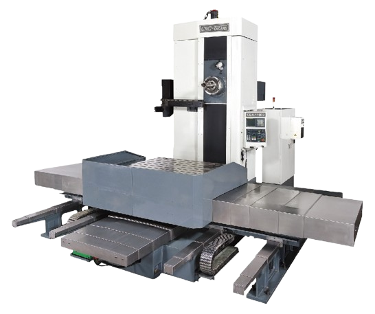
BORING MACHINE
STANDARD ACCESSORIES
1. FANUC Control Motors
2. 4” Spindle Bore
3. Auto 4 Steps Spindle Speed Change
4. H4 0r V8 Turret
5. Auto Coolant, Hydraulic and Lubrication System
6. Splash Guard
7. Hydraulic Tailstock
8. Work Light
9. Tool Box with Tools
OPTIONS
1. Extra Spindle Bore and Motor
2. Spindle Oil Chiller
3. Hydraulic / Manual Chuck
4. C Axis or Spindle 1/15 Degree Indexing
5. Driving tool Turret
6. Steady Rest
7. Follow Rest
8. Special Boring Bar Holder
9. Higher Coolant Pressure
10. Chip Conveyor
11. CE Mark
12. Transformer
CBA Series 2
| T - TYPE | CBA-135TR | CBA-135TR2 | CBA-135TR3 | CBA-135TR4 | |||
| Spindle | Main motor (cont. / 30 min) | kw | AC 37 / 45 | ||||
| Spindle speed (Max.) | rpm | P : 5 - 2000, Q : 5 - 1200 (P : w / o Quill Q : Quill) | |||||
| Spindle tapper | ISO 50 / BT-50 | ||||||
| Spindle diameter | mm | Dia. 135 | |||||
| Spindle end diameter | mm | Dia. 215 | |||||
| Quill diameter (W2) | mm | Dia. 380 (OPT.) | |||||
| Max. spindle torque | Nm | 2150 | |||||
| Travel | Work table travel X axis (Horizontal) | mm | 1500 | 2000 | 3000 | 4000 | |
| Spindle travel Y axis (Vertical) | mm | 1500 | 1800 | 2300 | 2800 | ||
| Column moving travel Z axis | 1100 | 1100 | 1400 | 1700 | |||
| Spindle travel W1 axis | mm | 700 | |||||
| Quill travel W2 axis | mm | 350 | |||||
| Total spindle travel (W1 + W2) | 1050 | ||||||
| Distance from spindle nose to table center | mm | 885 - 1985 | 885 - 1985 | 885 - 2285 | 885 – 2585 | ||
| Distance from spindle center to table surface | mm | 0 - 1500 | 0 - 1800 | 0 - 2300 | 0 - 2800 | ||
| Rotary table | Table dimension | mm | 1250 x 1400 | 1400 x 1600 | 1600 x 1800 | 1800 x 2000 | |
| T-slot | mm x No. | 22 x 7 | 22 x 9 | 22 x 9 | 22 x 9 | ||
| Max. loading weight | kg | 6500 | 8500 | 10000 | 12000 | ||
| Index | degree | 0.001° | |||||
| Max. rotation dimension | mm | 1877 | 2126 | 2408 | 2691 | ||
| Table rotation speed | rpm | 0.8 | |||||
| Feed | Rapid feed | XYZW1 axis | mm / min | XY axis = 8000 / W1 axis = 3000 / Z axis = 5000 | |||
| Feed rate | X / Y / Z axis | mm / min | 1 - 5000 | ||||
| W1 axis | mm / min | 1 - 3000 | |||||
| Quill feed rate | W2 axis | mm / min | 1 - 1500 | ||||
| Power capacity | KVA | 110 | 130 | 130 | 140 | ||
| Machinedimension(LxW xH) | mm | 6750x6950x4700 | 6900x7100x4900 | 7500x7500x5500 | 7850x7850x5950 | ||
| Machine weight | kg | 34500 | 39500 | 45000 | 49000 | ||
| Controller | Fanuc / Siemens / Heidenhain | ||||||
| *Specifications are subject to change without prior notice | |||||||
STANDARD ACCESSORIES
1. FANUC Control Motors
2. 6” Spindle Bore
3. H4 0r V8 Hydraulic Turret
4. Auto Coolant, Hydraulic and Lubrication System
5. Box way on Cross Slide
6. Splash Guard
7. Hydraulic Tailstock with Rotating Quill
8. Chip Conveyors (Auger for front and chain for rear)
9. Work Light
10. Tool Box with Tools
OPTIONS
1. Extra Spindle Bore, Motor and Speeds
2. Spindle Oil Chiller
3. Hydraulic / Manual Chuck
4. Face Plate
5. C Axis or Spindle 5 / 15 degree indexing
6. Y Axis
7. Driving Tool Turret
8. Steady Rest, Follow Rest ( Hydraulic or Manual)
9. Special Boring Bar Holder
10. Heavy Duty Milling Attachment
11. Grinding Head on Turret or Cross Slide
12. Tool Presetter
13. Higher Coolant Pressure
14. Cutting Pass Through Steady Rest Equipment (LC Only)
15. CE Mark
16. Transformer