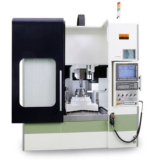
GROOVE GRINDER
CTG-540GCB - Heavy duty model
| Electronic control system | |
| NC controller | 0i-MF |
| Table | |
| Working surface | Ø400 mm |
| Max. Table load | 400Kg / 880ibs |
| Travel | |
| Longitudinal travel (X) | 850 mm |
| Cross travel (Y) | 600 mm |
| Headstock travel (Z) | 100 mm |
| Headstock travel (W) | 400 mm |
| Spindle | |
| Spindle speeds | 12000 R.P.M (m/s) |
| Spindle output | 1.5 Kw |
| Diameter of grinding wheel | Ø150 mm,Ø50 mm |
| Feed | |
| Feed rate | 1-12000 mm/min |
| Rapid traverse (X, Y, Z) | 24x24x24 m/min |
| Motors | |
| Spindle drive motor | CW-JG-12X 1.5KW |
| Drive motors | FANUC |
| Machine weight, space and packing | |
| Floor space (W x L) | W=2211mm L=3251mm |
| Max. Machine height | 3105 mm |
| Power capacity | 25 KVA |
| Net weight | 7000 Kg |
A jig grinder is a machine tool used for grinding complex shapes and holes where the highest degrees of accuracy and finish are required.
The jig grinder is very similar to a jig borer, in that the table positioning and spindles are very accurate (far more than a manual milling machine or lathe).
It is almost used by tool and die makers in the creation of jigs or mating holes.
There are usually many peripheral elements to a jig grinder, including linear motors, pneumatic grinding head (or electrical grinding head), and various cooling systems for supplying coolant to the work and machine itself.
The machine operates by a high speed spindle rotation.
The spindles are removable and interchangeable to achieve varying process speeds.
Some spindles are fixed speed (60,000 rpm), others are adjustable (30,000 ~ 50,000 rpm), and still others are very high speed (150,000 rpm).
The main spindle has a wide range of speeds to ensure proper grinder feed rates are maintained.
The machines have a standard X and Y table.
All axes are indexed to 0.0001 on the handwheels.
The machine head adopts linear motors.
The spindle rotates at a variable speed and with an accuracy of 0.0001 for very precise holes and grinding.
A reliable jig grinder will let work to achieve a higher degree of efficiency level.
These features are all critical in precise process.
STANDARD ACCESSORIES
1. FANUC Control Motors
2. 4” Spindle Bore
3. Auto 4 Steps Spindle Speed Change
4. H4 0r V8 Turret
5. Auto Coolant, Hydraulic and Lubrication System
6. Splash Guard
7. Hydraulic Tailstock
8. Work Light
9. Tool Box with Tools
OPTIONS
1. Extra Spindle Bore and Motor
2. Spindle Oil Chiller
3. Hydraulic / Manual Chuck
4. C Axis or Spindle 1/15 Degree Indexing
5. Driving tool Turret
6. Steady Rest
7. Follow Rest
8. Special Boring Bar Holder
9. Higher Coolant Pressure
10. Chip Conveyor
11. CE Mark
12. Transformer