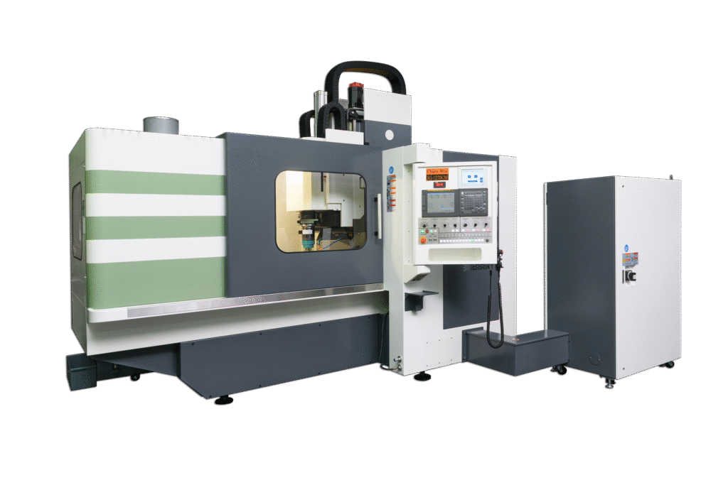
Precision Jig Grinder
STANDARD ACCESSORIES
1. FANUC Control Motors
2. 4” Spindle Bore
3. Auto 4 Steps Spindle Speed Change
4. H4 0r V8 Turret
5. Auto Coolant, Hydraulic and Lubrication System
6. Splash Guard
7. Hydraulic Tailstock
8. Work Light
9. Tool Box with Tools
OPTIONS
1. Extra Spindle Bore and Motor
2. Spindle Oil Chiller
3. Hydraulic / Manual Chuck
4. C Axis or Spindle 1/15 Degree Indexing
5. Driving tool Turret
6. Steady Rest
7. Follow Rest
8. Special Boring Bar Holder
9. Higher Coolant Pressure
10. Chip Conveyor
11. CE Mark
12. Transformer
JG-1270 CM - Heavy duty model
| Work range of the slides | |
| Range of movement | |
| X Axis | 1200 mm (47.2" ) |
| Y Axis | 700 mm (27.6" ) |
| Z Axis | 100 mm (3.9" ) |
| W Axis | 360 mm (15.7" ) |
| Max feed speed | |
| X,Y Axis | 10 m/min |
| Z Axis | 24 m/min |
| Reading resolution (Linear scales) | |
| X,Y Axis | 0.05 um |
| Z Axis | 0.05 um |
| Cs Axis | 0.001 deg |
| Location accuracy | |
| X,Y Axis | ±0.0025 mm |
| Position coder | |
| X,Y Axis | Linear encoder |
| Z Axis | Linear encoder |
| Cs Axis | Magnetic sensor |
| Table | |
| Table area (LxW) | 1280x860 mm (50.4"x33.9") |
| Permissble load (max.) | 1000 kg |
| Work range of the grinding head | |
| Grinding-spindle speeds | |
| Electrical grinding head | 40000 rpm |
| Weight | 11.5 kg |
| Max. diameter of wheel | Ø3~Ø55 mm |
| Electrical grinding head | 60000 rpm |
| Weight | 11.5 kg |
| Max. diameter of wheel | Ø1~Ø10 mm |
| Planetary speed | 5~200 rpm |
| Bore-diameter capacity | 1~100 mm (0.04"~3.9") |
| U axis last input increment | 0.001 mm |
| U axis max. stroke | 30 mm (1.18") |
| Outer dimensions and weight | |
| Length | 3392 mm |
| Width | 2609 mm |
| Height (Max.) | 3000 mm |
| Height (Min.) | 2750 mm |
| Weight | 7200 mm |
| Power requirement | |
| Voltage | 220v ± 10% |
| NC controller function | |
| NC controller | Fanuc 31i-B |
A jig grinder is a machine tool used for grinding complex shapes and holes where the highest degrees of accuracy and finish are required.
The jig grinder is very similar to a jig borer, in that the table positioning and spindles are very accurate (far more than a manual milling machine or lathe).
It is almost used by tool and die makers in the creation of jigs or mating holes.
There are usually many peripheral elements to a jig grinder, including linear motors, pneumatic grinding head (or electrical grinding head), and various cooling systems for supplying coolant to the work and machine itself.
The machine operates by a high speed spindle rotation.
The spindles are removable and interchangeable to achieve varying process speeds.
Some spindles are fixed speed (60,000 rpm), others are adjustable (30,000 ~ 50,000 rpm), and still others are very high speed (150,000 rpm).
The main spindle has a wide range of speeds to ensure proper grinder feed rates are maintained.
The machines have a standard X and Y table.
All axes are indexed to 0.0001 on the handwheels.
The machine head adopts linear motors.
The spindle rotates at a variable speed and with an accuracy of 0.0001 for very precise holes and grinding.
A reliable jig grinder will let work to achieve a higher degree of efficiency level.
These features are all critical in precise process.